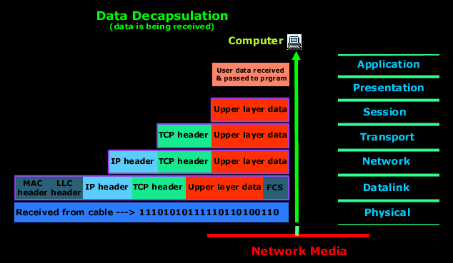
What is Encapsulation in OSI?
Encapsulation in the OSI (Open Systems Interconnection) model refers to the process of adding headers and trailers to data as it moves down through the layers of the OSI model on the sender's side. This process ensures that data is properly packaged for transmission across a network and can be correctly interpreted by the receiving device.
The OSI model consists of seven layers, each with specific responsibilities. Encapsulation occurs as data passes from higher layers (closer to the user) to lower layers (closer to the physical transmission medium). Each layer adds its own specific information, such as addressing or error-checking details, which are necessary for successful communication.
Step-by-Step Explanation of Encapsulation in OSI
1. Application Layer (Layer 7)
- At this highest layer, raw user data is generated by applications like email clients, web browsers, or file transfer programs.
- No additional headers or trailers are added at this stage in the OSI model; instead, this layer provides services like file transfers or email composition.
- The data is passed down to the Presentation Layer.
2. Presentation Layer (Layer 6)
- The Presentation Layer ensures that data is in a format understandable by both sender and receiver systems.
- It may perform encryption, decryption, compression, or translation tasks.
- Once formatted appropriately, the data is sent to the Session Layer.
3. Session Layer (Layer 5)
- This layer establishes and manages sessions between devices for ongoing communication.
- It adds session-related information to ensure proper synchronization and flow control during communication.
- After this step, encapsulated session-layer data is passed down to the Transport Layer.
4. Transport Layer (Layer 4)
- The Transport Layer breaks down large chunks of data into smaller segments for efficient transmission.
- It adds a header containing critical information such as:
- Source port number
- Destination port number
- Sequence numbers for reordering packets at the destination
- Error-checking mechanisms
- Depending on whether TCP (Transmission Control Protocol) or UDP (User Datagram Protocol) is used:
- If TCP: The encapsulated unit is called a "Segment."
- If UDP: The encapsulated unit is called a "Datagram."
The segment/datagram is then passed down to the Network Layer.
5. Network Layer (Layer 3)
- The Network Layer handles logical addressing and routing of packets across networks.
- A header containing source and destination IP addresses is added here.
- After encapsulation at this layer:
- The encapsulated unit becomes known as a "Packet."
The packet proceeds to the Data Link Layer.
6. Data Link Layer (Layer 2)
- This layer prepares packets for delivery over physical media by adding both a header and a trailer:
- Header: Contains source and destination MAC addresses for local delivery within a network segment.
- Trailer: Includes error-checking information like CRC (Cyclic Redundancy Check).
After encapsulation at this stage:
- The encapsulated unit becomes known as a "Frame."
The frame moves on to the Physical Layer.
7. Physical Layer (Layer 1)
- At this lowest level of abstraction, frames are converted into electrical signals, light pulses, or radio waves depending on the medium used for transmission.
- Encapsulation here involves converting frames into binary bits—0s and 1s—that represent electrical charges or other forms of signal encoding suitable for transmission over cables, fiber optics, or wireless mediums.
Key Characteristics of Encapsulation in OSI
-
Protocol Data Units (PDUs): Each layer has its own name for its encapsulated data:
- Application/Presentation/Session Layers: Data
- Transport Layer: Segment/Datagram
- Network Layer: Packet
- Data Link Layer: Frame
- Physical Layer: Bits
-
Headers and Trailers: Headers are added at every layer except at Layers 7–5 in most implementations. Trailers are typically added only at the Data Link layer for error detection purposes.
- Purpose: Encapsulation ensures that each layer performs its specific function while maintaining compatibility with other devices using standardized protocols like TCP/IP.
- Reverse Process – De-encapsulation: On reaching its destination, de-encapsulation occurs as data travels upward through each OSI layer on the receiving device. Headers/trailers are stripped off one by one until only raw user data remains.
Example of Encapsulation
Consider sending an email:
- At the Application layer: You compose your email message using an application like Outlook.
- At subsequent layers:
- Transport adds port numbers via TCP/UDP headers.
- Network adds IP addresses via an IP header.
- Data Link adds MAC addresses via Ethernet headers/trailers.
- Physical converts all these into binary signals transmitted over cables/wireless media.
When received by another computer:
- De-encapsulation begins at Physical and works upward until your email client displays your message intact.
Importance of Encapsulation
Encapsulation plays several critical roles in networking:
- Data Integrity: Ensures that transmitted data reaches its intended recipient without corruption through error-checking mechanisms like CRCs.
- Addressing: Adds logical (IP) and physical (MAC) addresses so devices know where to send/receive packets within local/global networks.
- Interoperability: Allows devices from different manufacturers adhering to standard protocols like TCP/IP or Ethernet to communicate seamlessly.[1] [2] [3]
Authoritative Sources
- GeeksforGeeks article on how encapsulation works [GeeksforGeeks]↩
- TechTarget introduction to encapsulation [TechTarget]↩
- Study CCNA explanation on encapsulation [Study CCNA]↩


0 comments:
Post a Comment